June 2008
2008 June VHF QSO Party Report
The Preparation:
 In between each contest we start months in advance determining what changes we want to make. These changes range from fixing problems that have cropped up over time or the addition of new bands to improve our capabilities.
The first major change was the addition of 3.4 ghz. The Down East Microwave transverter was ordered in November of 2007. It didn’t arrive until the end of April. We also ordered a Directive Systems 3.4ghz looper. Those loops are tiny at 3.4 ghz. ![]() In order to mount the antenna we needed to fix a few problems with a sub-mast that we installed using these curly-Q bolts that we got from WB0W.com. They are absolutely worthless. They are supposed to allow you to clamp together two small perpendicular masts(one horizontal/one vertical). They do just that but not unless you crush the mast in the process. They just have no way to grip on the masts and thus to get it tight enough so they won’t slip it crushes the pipe. We ordered some aluminum plates and stainless steel u-bolts and made up our own square plates. Drilled them out and that did the trick. This will keep the 1296 looper from pointing up in the air 😉 Mounted the new antenna up on the mast and dressed the coax down the mast and into the back of the RV.
In order to mount the antenna we needed to fix a few problems with a sub-mast that we installed using these curly-Q bolts that we got from WB0W.com. They are absolutely worthless. They are supposed to allow you to clamp together two small perpendicular masts(one horizontal/one vertical). They do just that but not unless you crush the mast in the process. They just have no way to grip on the masts and thus to get it tight enough so they won’t slip it crushes the pipe. We ordered some aluminum plates and stainless steel u-bolts and made up our own square plates. Drilled them out and that did the trick. This will keep the 1296 looper from pointing up in the air 😉 Mounted the new antenna up on the mast and dressed the coax down the mast and into the back of the RV.
We decided to look into identifying why we were not getting full power out on our 2 meter amp. It turns out that we were experiencing significant voltage drop when drawing the 54 amps required for the amp. To combat this, Brian Skutt (ND3F) donated some rather large size 2 or 00 cable and and 1/4″ lugs. We soldered the terminal lugs on the cable and did some tests. We still experienced some voltage drop but now it was maintaining voltage above 14.0v and the amp was putting out 400 watts easily with 25 watts input
 We also purchased a 6 meter amplifier. It is a TE Systems 0552G 400W amplifier. We made up some short runs of #4 cable and connected it to the terminal posts on the back of the 2 meter amplifier for power.
During the last contest we had problems with the 1296 SWR being slightly high. This prevented us from running the full 120 watts. We assumed the problem was the antenna. After all it was beaten to death several times by trees on previous roves. The spacing of the elements around the driven element or the gap on the driven element for the match had to be wrong. It turned out the antenna was actually fine and that our brand new LMR-600 coax had a problem about 3-4 inches back from the connector at the antenna. Because this was found at the last moment before the contest we decided to try to live with it. When we reattached the antenna and tested, everything appears to be okay.
We also had another problem with the 222 Mirage amp. The amplifier requires 2 watts input for 110 watts output. During the sprints we decided to look at the power levels and discovered the transverter was putting out over 3 watts when running our normal 8 watts input. This was probably due to setting the input attenuation to give 2 watts out while running on a battery instead of the 14.2 regulated supply it runs on currently.
The weekend before the contest we completed two little relay projects. We recently discovered that the TS-2000x’s PTT circuit could only handle a max of 20ma. This was especially a concern when we discovered the relays on most of the Down East Microwave transverters drew about 25ma. Fortunately, this never caused us a problem. The issue came to our attention when we were looking into integrating a 40 watt Toshiba amplifier for 3456 which will be waiting until September now. We built a PTT isolator box from a circuit that Down East Microwave sells. The board comes with 5 relays and draws about 2ma well under the max of 20ma that the TS-2000 and must modern rigs can handle. The relays on this board are DPDT and will handle up to 3amps. This works really nice.
 We also installed an Ameritron RCS-8V Remote Antenna Selector. Since our second TS-2000 runs 903 through 3.4ghz, we have two transverters that both have a 144Mhz IF. The Ameritron is a 5 position remote coax switch. We are using position 1 for 2.3ghz , 2 for 3.4 ghz, 3 and 4 will eventually be 5g and 10g. Position 5 we are using to connect back to the square loop at the front of the RV. In the future we are going to put a 160watt amp inline on that 2 meter pass through port. The idea is to run all our microwave equiptment at 8 watts input so that we do not run the risk of blowing something up by changing powers. In order to make this happen, we also needed to build and install PTT relays to select which transverter the PTT line is connected to. The Ameritron outputs 12v on the selected port which engadges that coax relay. We attached our relay box in parallel and thus the appropriate relay is engadged depending on what position the switch is in. It’s all really cool. Next, we had to make up a few PTT lines to hook the ts-2000x up to the PTT isolator box for 28Mhz IF, 144Mhz IF and 1296. The TS-2000x used to be hooked up to 1296 but the 28Mhz and 144Mhz IF’s were previously attached to the IC-706. The idea here is to eliminate the need for a third radio on the already compact table.
 We then had to make some adjustments to our two transverters. Our 2304 transverter/amp was originally put together by WA3PTV. Joe used a DEM TC board with a 10 watt input attenuator. It is a combination of a transmit and receive modules from SSB electronics and a pyrojoe 2.4ghz 60 watt amp board. Originally it was setup for 2 watts input gave you 40 watts out on the amplifier. Since we do not own a bird element for that band we made some relative power settings and adjusted it so the transverter would take 8 watts input. This is our standard that we follow for all transverters in the rover. We then adjusted the brand new 3.4ghz DEM transverter as well. Since the Bird isn’t rated above 2500 Mhz we simply used it to take some relative readings. To make sure we didn’t excede the limits for the transverter we monitored the supply current to ensure it remained below the max rated current draw of 1 amp. We believe we are close to 1 watt out. Now that the two 2m IF transverters were adjusted, we installed them back into their rack. The 3.4ghz went to the very top shelf and unfortunately the 2.3ghz transverter went to the floor of the closet. This is a temporary solution until I get a brand new 2.3ghz transverter that I have ordered from DEM. We also ordered another one of those amp boards so I can put together a nice compact package to run everything.
 Sunday afternoon, Dave contacted Dave Petke K1RZ who lives about 17 miles away in Damascus to run a test on 3.4ghz. We ran the test and copied Dave loud and clear on CW and he heard as well. We were only running 1 watt up 42 feet of LMR-600 which ends up being almost 1/2 a watt at the antenna. The antenna is a 23dbi gain looper antenna from Directive Systems. Doing the math that is about 100 watts ERP. No where near as much as our other bands but it appears to be working. A little later after dinner, Dave hooked up a few other bands to run some tests as K1RZ wanted to run some additional tests on 3.4ghz. Jim (K3LFO) and Dave(K1RZ) tested 1296 through 3456 and then had about a 40 minute ragchew on 3456.
The one thing we are learning about the higher in frequency you go is you need to search around more to find the station you are trying to work. We found Dave about 18khz below what his IF frequency was set to. This could be a number of factors, both of our transverters could be a little off adding to 18khz or one of us could be way off. It seemed to drift and close the gap a little bit after about 20 minutes of warm up. A few days later we decided to check the calibration on our new 3.4ghz transverter. We transmitted a carrier on 144.010 on one rig and listened for the 24th harmonic on 3456.240. We found that the transverter was 17.47khz high. This explained the difference in frequency from K1RZ. We decided to wait until after the contest to adjust the calibration
We originally were planning on running some power cables to add battery back up to the back systems but unfortunately didn’t get all the relevant pieces together in time. We may try to install this in between the June contest and Field Day.
The Equipment:
|
|
| Device | Description of use |
|---|---|
| Ameritron RCS-8V | This is being used as a 144 Mhz IF switch between 2 meters to a square loop, and a 2304 and 3456 transverter. |
The Configuration:
| Band | Power | Antenna |
|---|---|---|
| 6 meters | 400W | PAR Slightly UN-Stressed Moxon |
| 6 meters (Secondary) | 100W | M2 6M HO LOOP |
| 2 meters | 400W | Directive Systems DS144-6RS |
| 2 meters (Secondary) | 8W | M2 2M HO LOOP |
| 1 1/4 meters (222) | 110W | Cushcraft 11 Element |
| 70cm (432) | 185W | Directive Systems DSFO432-15RS |
| 70cm (432 Secondary) | 50W | M2 432 HO LOOP |
| 33cm (903) | 30W | Directive Systems 3333LY 33 Element Looper |
| 23cm (1296) | 150W | Directive Systems 2345LY 45 Element Looper |
| 13cm (2304) | 60W | Directive Systems 1345LY 45 Element Looper |
| 9cm (3456) | 1W | Directive Systems 976LY 76 Element Looper |
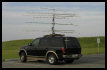
A new Directive Systems 76 Element Looper (976LY) was acquired and installed on the mast.
The Trip:
FM27BX:
 We started the contest down in Crisfield, Maryland in a parking lot right off the bay. Unfortunately, it takes over 3 hours to get there. We left the K3LFO home QTH right around 9:30am and went about 1 mile down the street to fill the gas tank. We finally arrived in Crisfield right around 1:30pm. We positioned the rover pointing due north and raised the antennas. When the start of the contest arrived, We immediately began trying to work people. Unfortunately, even though we announced our plans for this rove not too many people were pointing our way since we are far away from a regular amateur radio population center. Not too much longer and we had completed all bands successfully with Dave K1RZ who as usual was keeping a look out for us. After an hour, we had only made 23 contacts we decided it was time to move on.
FM28AW:
 It took about 2 1/2 hours to get there but we arrived in our operating location in FM28 at an Army Reserve Center at the corner of 404 and 309. Again, not a spectacular location but it has the distinct charm of being used multiple times without anyone bothering us or shooing us away. We setup and operated for just over an hour and made only 29 contacts. Things were really slow going. We were not experiencing any E or tropo. Things were just dead. We decided to move on to the next grid which was only 15 minutes away.
FM29AA:
 This site is the parking lot of a little community center off of Route 481 which is only a few minutes away from the last grid. We once again raised the mast and got back on the air. We worked as many people as we could before a thunderstorm came through the area. Dave quickly got out and lowered the mast back down and we waited the storm out. We decided we were done in this grid but had not heard K1RZ on and wanted to make sure we worked him on all bands before we moved on to the next grid. We moved the RV and pointed it on a heading directly lined up towards K1RZ’s QTH. We then contacted him on his 2 meter frequency. We worked him on all bands with ease even with the antennas laying down on the roof. We made use of the 6 and 2 meter square loops which are the only bands that are effected by high SWR when the antennas are layed down. We again only made about 30 contacts.
FM18UX:
 Prior to the contest we had used google maps scout out a good location just inside FM18 on the east side of the bay bridge. We had identified 3 potential sites near the Bay Bridge Airport off of Route 37. We decided we would try a parking lot that was adjacent to the runway. We got setup and back on the air and worked a bunch of people for 20 minutes before we realized 6 meters was open. We jumped on the band wagon and tried to work as many people as possible. Again even with a little opening on 6 meters we only made about 45 contacts. It was 11:30pm and we were getting tired. We had a few hours to go to get back to Dave’s QTH so we decided to get moving.
FM19JJ:
 We arrived at Dave’s QTH and it was a little later than we had planned. It was 1:30am and both of us were extremely tired. We decided to scrap the idea of working any digital modes and headed to bed.
In the morning, we got up and Dave headed out to make some contacts. We were attached to the house power overnight to run the refrigerator and when we started at first, we were still connected. So with no surprise with the AC running in the RV and then keying down the breaker on that circuit popped. After a minute or so, we realized what had happened and went back in to reset the breaker. It wasn’t much later that it happened again so we fired up the generator and switched over to it. We got on 6 meters and heard it was open so began working as many people as we could. We made only about 57 contacts. We operated from 9am until noon before we decided to pack up and move on to our next grid.
FM09UR (Sidling Hill):
 Dave’s QTH is about an hour and a half from Sidling Hill. We got up there and set up. It wasn’t long before we realized that there was something wrong with the 6 meter square loop. We swapped out the cables on the inside and improved the situation slightly but the SWR was still 3:1. The change in SWR was most likely only caused by the change in length of coax. We decided it wasn’t important to resolve this issue this weekend so we used the tuner and kept on making 6 meter contacts on the secondary rig while the primary was busy on 2 meters. We only made about 42 contacts when it was almost 4pm. We had operated for only about 2 hours but we needed to get moving so we could spend as much time on Skyline Drive as possible.
FM08US (Hogback Overlook):
 Our final stop was at the Hogback overlook on Skyline Drive in FM08US. We originally were planning on stopping at a few other overlooks but when we got there it was already 7:35pm and only a little over 3 hours to operate so we decided to go directly to Hogback. We also took a few minutes to take some pictures and enjoy the scenary.
We hopped back in the RV and got on the air. We again completed on all bands with Dave K1RZ. We even completed on all bands with K8GP which hadn’t happened from the other grids. 6 meters had opened up a little bit again. We made 99 contacts from Hogback of which only 30 were on 6 meters
Summary:
 Saturday was a very long and hot day and it didn’t help that band conditions were very flat with the exception of some very sporadic E on 6 meters. On Sunday things were only marginally better for us. The E on 6 helped our multiplier counts but only slightly helped our QSO count. Our QSO count on the other bands suffered either due to everyone being on 6 or the extra time taken to attempt to complete QSO’s on 1296 through 3456. We still experience a few interference issues between the two radios but more importantly both rigs cannot transmit at the same time when on certain band combinations due to available current from the Astron RS-70M power supply. We were able to atleast operate on 2 and 6 meters at the same time with 6 meters using the square loop without causing too much interference to each other.
Again a special thanks goes out to Dave Petke (K1RZ) who always keeps an ear out for us when we are out roving. We completed with K1RZ on all bands from all grids. That’s 56 contacts!!! Dave recently had replaced his tower and had done a great deal of improvements to his already amazing station up on the Ridge in Damascas FM19JH.
We once again had a tree strike free rove!!! It’s so nice to be able to come home and not have to worry about replacing elements on beams. The only damage we suffered was from wind while driving which bent over the last director at the end of the 1296 looper. This has happened every rove and quite simple to correct.
Even though we only had 1 watt on 3456 we were successful in making contacts and with the exception of our calibration issues, the new transverter appears to be functioning admirably. Our new PTT isolator relay box and relay switch boxes for the 2 meter IF worked fabulously. It was quite nice to be able to switch between 2 meters, 2304 and 3456 with a turn of a knob. It was also nice to only have two radios at the table instead of 3. It made it a little more comfortable at the operating table.
The Results:
2008 ARRL June VHF QSO Party            K3LFO

ROVER                            MDC Section

Band      QSOs          QSO pts.      Mults.
--------------------------------------------
50         114           114           40
144        68            68            18
222        37            74            11
432        44            88            13
903        20            60            7
1296       24            72            7
2304       10            40            4
3456       9             36            3
--------------------------------------------
TOTALS     326           552          103 + 7 = 110

Claimed score = 60,720

[…] Contest ReportsJune 2008 […]
Pingback by K3LFO/W3DIO Rover Site — June 17, 2008 @ 8:21 pm