Choosing the right wire size!!!
Add a little line resistance, about 54 amps of current and wah-lah you get just over 1 volt drop. In our rover we are using a DC Power 75-amp powerpole distribution block. Being rated to handle up to 75 amps of current it is connected to the power supply with a #6 wire. 4/10th of a volt drop is just from that wire and the junction across the fuses. The rest is the number 8 wire going the rest of the way to the amplifier which has about 5 feet of wire. Unfortunately a large portion of this loss appears to be coming from the crimp-on 75amp powerpole connectors. The solution? Unfortunately our nifty little power distribution block needs to be removed from the picture and we are going to have to use larger wire directly to each of the high power amps.
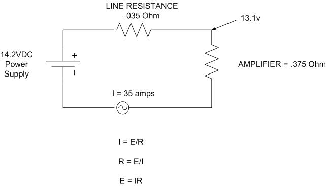
Why is this an issue? We found that our brand new TE Systems 0552g 6 meter 400 watt amplifier puts out about 270 watts when driven to maximum input power of 25 watts. This is caused by the losses we incur from the line resistance. We verified that the power supply itself is still regulating at 14.2v. Therefore the only solution is to increase the wire size and only used soldered connections as some loss may be caused by the crimp on powerpole connections. We also found our TE Systems 1452G 2 meter 400 watt amplifier puts out about 280 watts when drive with its maximum input power of 25 watts.
So two weeks ago dad soldered up, using the propane torch, some rather hefty terminals on the end of some rather large (size 00) welding cable that Brian Skutt(ND3F) donated for the cause. Since the wire and terminal lugs on it are quite large, I used some 1″ shrink wrap around it to help prevent accidental shorts. I found that the hairdryer I was using worked well to get most of the job done and shrunk the heat shrink evenly. I followed up by waving the propane torch across it which smoothed out any bumps or bubbles and make it look really nice and a tight fit around the wire. I then went back to the RV to test it out. Unfortunately the terminals (1/4″x20) on the power supply aren’t long enough to just add this connector on so at Dad’s suggestion I replaced the brass terminals that were 1 1/4″ long with 1 1/2″ long terminal bolts. We then wired it up to the 2 meter amp. I hooked the bird watt meter and bird dummy load in line on the output and gave it a try with just 5 watts input. I was shocked to see about 290 watts output. This is more than we’ve ever seen with the max 25 watts input. At 10 watts input it puts out over 300 watts. At 18 watts the amp is putting out 400 watts and at 25 watts it now puts out about 420 watts. WOW. What a difference. When we measured the voltage at the amp DC power terminals while transmitting we read 14.06v. WOW.. The only way to improve that would be to run a sense line from the power supply out to the amplifier but I think 14.06v is perfect. Really impressed. In fact this is the very first time we have ever seen the rated power output of this amp. When I bought this amp they rated it at 400 watts and then shortly afterwards changed their ads to say 375. I dont know if the model I have is only supposed to do 375 or not but it seems to work. We tend to be a little conservative on amp power anyhow so we will probably run it anywhere from 10-18 watts input.
Now I need to replace a cross-threaded ground terminal on the new 6 meter amp and then install it on it’s shelf rails. The idea is we will run the #00 wire to the two meter amp in the RF closet and then from there run a #4 wire the few feet from there to the 6 meter amp. We also need to eventually replace the 6 meter coax but more importantly we need to replace the 222 coax as it is just too short and the connector has intermittent connections with it’s shield. We also are still waiting on the 3456 transverter on order from Down East Microwave and have some antenna/mast work to do before the June contest.
Thanks Brian(ND3F/N3IQ) for all your help and your donations to the rover cause.